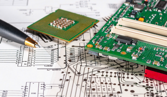
Automotive electronic control units must operate reliably amid vibration, temperature changes, electrical noise, and safety expectations. Their circuit boards connect processors, sensors, actuators, and communication interfaces, making layout and component choices important. PCB design services can help translate vehicle-level requirements into board-level decisions, from circuit partitioning to manufacturing readiness, while keeping performance, cost, and reliability in view.
A sound ECU board begins with its operating environment, not just its schematic. Engineers need to understand power sources, signal types, enclosure limits, and vehicle networks before fixing the architecture. These inputs guide component selection, routing strategy, protection, and validation. Planning reduces avoidable redesign and supports consistent behavior across production units and vehicle conditions.
Establish the ECU’s Electrical and Environmental Context
An ECU’s function determines its hardware priorities. A body control module may manage switches, lighting, and motors, while a powertrain controller may process fast sensor signals and control demanding loads. Each use case brings different current levels, timing needs, interfaces, and consequences of failure.
Translate vehicle requirements into measurable board constraints. Define supply ranges, transient exposure, operating and storage temperatures, connector assignments, signal bandwidth, communication protocols, and available board area. Include the expected mounting position and enclosure because heat, moisture, and vibration vary across the vehicle. These details form the basis for design reviews and verification criteria.
See also: Top Seoul Travel Attractions Nobody Should Miss
Shape the Circuit and Component Architecture
Circuit architecture determines how power, processing, sensing, and communication functions interact. Partitioning high-current paths from sensitive analog circuitry can reduce interference, while clear functional boundaries simplify troubleshooting. A PCB design company should consider these relationships early rather than treating placement and routing as isolated tasks.
1. Select Automotive-Grade Components
Choose components according to required temperature range, qualification status, lifecycle, availability, and electrical margins. Review data sheets for derating guidance, package limitations, and failure behavior. Automotive-grade parts can support demanding conditions, but the complete board still needs engineering validation as intended.
2. Design the Power-Entry Stage
The power-entry circuit must accommodate normal operating voltage as well as expected disturbances. Protection and filtering may include reverse-polarity safeguards, transient suppression, input filtering, and controlled startup. Component ratings should reflect the vehicle’s electrical environment and the energy each device may need to absorb or dissipate.
3. Separate Sensitive and Noisy Functions
Switching regulators, motor drivers, and fast digital interfaces can generate noise that affects analog measurements or radio-frequency circuits. Place noisy sources with their return paths in mind, and keep sensitive inputs away from high-current switching loops. Partitioning should preserve short, predictable signal paths without creating fragmented reference planes.
4. Plan Connectors and Service Access
Connector selection affects current capacity, sealing, retention, pin assignment, and assembly. Group related signals logically and consider harness routing, mating cycles, and service access. Provide suitable test points where they can be reached during production testing without compromising spacing, safety, or enclosure constraints.
5. Account for Mechanical Loads
Board shape, mounting holes, component mass, and connector forces influence mechanical reliability. Avoid placing fragile components near stress concentration points, and review unsupported board edges and heavy parts. Coordinate with enclosure and mounting design so the PCB does not become an unintended structural member.
Protect Power, Signals, and Communication Interfaces
Automotive boards must tolerate electrical disturbances while preserving useful signals. Protection strategy depends on the interface, expected fault, and system-level requirements. Engineers should consider transient energy, ground shifts, cable length, and the possibility of incorrect connections rather than selecting protection parts by voltage rating alone.
A practical design review should examine the following areas:
- Confirm power-stage ratings and thermal margins.
- Review transient and reverse-polarity protection.
- Check grounding and return-current paths.
- Verify differential-pair routing and impedance targets.
- Assess filtering for sensor and communication inputs.
- Check spacing, creepage, and connector pin assignments.
These checks help expose weaknesses before fabrication. Document assumptions and link each protection choice to the relevant requirement, so later changes can be assessed without losing the original engineering rationale.
Manage PCB Layout, Thermal Behavior, and Manufacturability
Placement and routing turn the circuit concept into a physical system. Stack-up selection should reflect signal speeds, impedance needs, copper weight, board thickness, and manufacturing capability. A continuous reference plane often improves return paths and reduces unintended coupling, while controlled routing supports sensitive or high-speed interfaces.
Thermal analysis is important when regulators, processors, drivers, or protection devices dissipate significant power. Estimate losses, identify heat paths, and assess copper areas, thermal vias, and component spacing. Validate assumptions through simulation or measurement when operating conditions make temperature a critical factor.
Manufacturability also belongs in the design process. Follow the fabricator’s design rules for trace width, spacing, drill sizes, solder-mask clearances, and copper balance. Consider assembly access, component orientation, inspection, and rework. Early design-for-manufacturing review can prevent a board that works electrically but is difficult to build consistently.
Validate the ECU Board Across Realistic Conditions
Validation should connect board-level tests with ECU behavior and vehicle requirements. Begin with visual inspection and electrical checks, then verify power sequencing, current consumption, clock activity, programming, and basic interfaces. Test representative loads and communication traffic before moving to more demanding environmental and fault scenarios.
Use a structured evidence plan to make results repeatable:
- Inspect fabrication and assembly against released files.
- Check continuity, shorts, and power-rail sequencing.
- Measure current draw across operating modes.
- Verify communication and sensor accuracy.
- Exercise fault responses and recovery behavior.
- Run thermal, vibration, and environmental tests as required.
Record board revision, firmware version, equipment setup, test conditions, and measured results. When a failure appears, preserve the setup and isolate whether its source is component behavior, layout, assembly, firmware interaction, or the test environment. This evidence supports corrective action and regression testing.
Conclusion
Reliable automotive ECU hardware depends on coordinated decisions across electrical architecture, component selection, protection, PCB layout, thermal management, manufacturability, and validation. Considering the vehicle environment from the beginning helps engineers prevent avoidable defects and build boards that can be tested, produced, and maintained with confidence.
Those who are looking for comprehensive test engineering services can consider Tessolve, which supports automotive and embedded engineering through design validation, verification, and testing expertise. Its engineering capabilities can help teams assess ECU performance, identify hardware risks, and strengthen confidence before product release.
